Circuits
Resistor Networks
Series resistors
Current divider
Voltage divider
Delta-Wye transformations
Wye to Delta
Millman's theorem
Ohm's Law
Capacitor Networks
L/C
For a series circuit of a resistor R, a capacitor C and
I = E/Z at angle θ
Rectifier and filters
Capacitor input filter, full wave
Sine Wave
120 volts 60 Hz mains
Power
P = E*I
AC Power
The product of voltage and current is the apparent
power in AC circuits. It does not take into account
that some of the apparent power can be reactive current
due to inductors or capacitors. If the load is truly
resistive, the true and apparent power are the same,
and the power factor is 1.
True power is important because that relates to the
mechanical power driving the generator, or produced by
a motor. Apparent power is important too, as it causes
extra current to flow in windings and cables, which
must be considered.
Generally the power factor is not always known but can
be estimated, taken from the nameplate of a motor, or
taken as a worst case of perhaps 0.8. Power factor is
the ratio of true power to apparent power, which is cos
(theta) where theta is the angle between the voltage
and current (this is a sine wave situation). Therefore
measuring the current to voltage phase angle can be
used to find the power factor. A true watt meter uses
an approach along these lines.
Single phase power is generally provided and calculated
by the line to neutral voltage, which is 230V in most
of the world. The line to line voltage is sqrt(3) *
phase to neutral voltage, around 400V for 230V systems,
or 415V for a 240V system. To calculate power in such a
system, use the line to neutral voltage always, even if
the connection is line to line. Thus 230V or 240V *
current in each line gives apparent power for each
line. Correct for power factor. Then add the three
powers.
Shockley diode equation
for n=1, we get the ideal diode equation
drift velocity Vd
Circuits
electronics
resistors
capacitors
Rt = R₁ + R₂ + R₃ + ...
Parallel resistors
1/Rt = (1/R₁) + (1/R₂) + (1/R₃) + ...
Rt = R₁R₂ / (R₁+R₂)
N resistors in parallel with current flowing into the junction
Ix = If•Rt / (Rx+Rt)
Rt is total resistance excluding Rx
Ix is current in branch with Rx
It is total current into the node
2 resistors in Series with voltage V applied to the pair.
Voltage across R₁:
V₁ = V(R₁) / (R₁ + R₂)
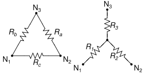
Delta to Wye
R₁ = (RbRc) / (Ra+Rb+Rc)
R₂ = (RaRc) / (Ra+Rb+Rc)
R₃ = (RaRb) / (Ra+Rb+Rc)
Ra = (R₁R₂+R₂R₃+R₁R₃)/R₁
Rb = (R₁R₂+R₂R₃+R₁R₃)/R₂
Rc = (R₁R₂+R₂R₃+R₁R₃)/R₃
For a circuit consisting of simple branches in parallel.
It provides the voltage across all the parallel branches.
Let Vk be the voltage generators and Am the current generators.
Let Ri be the R's on the branches with no generator.
Let Rk be the R's on the branches with voltage generators.
Let Rm be the R's on the branches with current generators.
The voltage at the ends of the circuit is given by:
V = [ Σ(Vk/Rk) + ΣAm ] / [ Σ(1/Rk) + Σ(1/Ri) ]
R is resistance in ohms, E is voltage in volts,
I is current in amps
E = IR I = E/R R = E/I
The superposition theorem for electrical circuits states that for a
linear system the response (voltage or current) in any branch of a
bilateral linear circuit having more than one independent source equals
the algebraic sum of the responses caused by each independent source
acting alone, where all the other independent sources are replaced by
their internal impedances.
Parallel capacitors
Ct = C₁ + C₂ + C₃ + ...
Series capacitors
1/Ct = (1/C₁) + (1/C₂) + (1/C₃) + ...
Capacitor: current leads the voltage or voltage lags the current
inductor: current lags the voltage or voltage leads the current
resonance, series
f = 1/(2π√(LC))
ω = 1/(√(LC))
Q = X/R, where X is either Xʟ or Xc
Q = f/Δf, f=resonant f, and Δf = bandwidth
an inductor L, the impedance may be calculated as follows:
Capacitive Reactance Xc = 1/(2πfC) = 1/ωC
Inductive Reactance Xʟ = 2πfL = ωL
Impedance Z = √(R² + X²)
where X = Xʟ – Xc
ω = 2πf
Phase angle θ = arctan (X/R)
Xc, Xʟ, Z are in Ω, f is in Hz
C in farads, L in Henrys
Vc = I*Xc laging the current by 90º
Vʟ = I*Xʟ leading the current by 90º
Vr = I*R in phase with current
voltage out of FW rectifier, no cap =
VDC = VAC x 1.414 x 2/π = 0.90 VAC (RMS)
Half wave is half that or 0.45 VAC (RMS)
Ripple voltage p-p = IT/C
V(RMS) is (0.29)(IT/C)
T = 8ms for 60Hz. I is load current
y(t) = A•sin(2πft + Φ) = A•sin(ωt + Φ)
A is amplitude (peak value)
f is frequency in Hz
t is time in seconds
ω = 2πf is angular frequency in radians / second
Φ is phase in radians
y = 170 sin 377t
There are three kinds of power
• real or resistive power (the only one that results
in heat)
• reactive power
• total power S, or apparent power, the vector sum of
the above two, or the product of the RMS voltage
and the RMS current
θ is the phase angle between the current and voltage
real power P = S cos θ
P = E²/R
P = I²R
1HP = 746 watts
1 amp = 1 coulomb per second = 6.242e18 electrons per sec
Real power (P) or active power[1]: watt [W]
Reactive power (Q): volt-ampere reactive [var]
Complex power (S): volt-ampere [VA] or apparent power
Apparent Power (|S|), that is, the absolute value of
complex power S: volt-ampere [VA]
Phase of Voltage Relative to Current (φ), the angle of
difference (in degrees) between voltage and current;
Current lagging Voltage (Quadrant I Vector), Current
leading voltage (Quadrant IV Vector)
Power Factor (PF) The ratio of real power to apparent
power and is a dimensionless number between 0 and 1.
True_power = apparent_power * power_factor (of the load)
I = Is(e^(Vd/nVt) – 1)
I is diode current
Is is reverse bias saturation current
Vd is voltage across the diode
Vt is the thermal voltage, 25.85 mV at 300 K
n is a quality factor, usually =1
Vt = kT/q
k is Boltzmann constant, 1.381e-23 J/K
T is temperature of junction in kelvins
q is charge on an electron 1.602e-19 C
Vd = I / nqA
Vd is drift velocity in m/s
I is current
n is the number of charge carriers per m³
for copper, 8.5e28 electrons per m³.
A = πr² is the cross sectional area in m²
q is the charge of the charge carriers (electrons)
q = –1.602e-19 Coulomb (charge on an electron)
Area, Volume
Atomic Mass
Black Body Radiation
Boolean Algebra
Calculus
Capacitor
Center of Mass
Carnot Cycle
Charge
Chemistry
Elements
Reactions
Circuits
Complex numbers
Constants
Curves, lines
deciBell
Density
Electronics
Elements
Flow in fluids
Fourier's Law
Gases
Gravitation
Greek Alphabet
Horizon Distance
Interest
Magnetics
Math Trig
Math, complex
Maxwell's Eq's
Motion
Newton's Laws
Octal/Hex Codes
Orbital Mechanics
Particles
Parts, Analog IC
Digital IC Discrete
Pendulum
Planets
Pressure
Prime Numbers
Questions
Radiation
Refraction
Relativistic Motion
Resistance, Resistivity
Rotation
Series
SI (metric) prefixes
Skin Effect
Specific Heat
Springs
Stellar magnitude
Thermal
Thermal Conductivity
Thermal Expansion
Thermodynamics
Trigonometry
Units, Conversions
Vectors
Volume, Area
Water
Wave Motion
Wire, Cu Al metric
Young's Modulus